Important! Read First!
- Never hotplug any connections except USB. Never connect or disconnect any cables except USB when power is ON. Always disconnect mains power before connecting or disconnecting the Master & Hub, and Slave Interconnect cables (Master Controller USB can always stay connected, this is the only exception).
- Never connect any DCSBIOSKit devices to your home network, such as routers or switches. DCSBIOSKit is not ethernet-compatible, permanent damage will occur.
- Never connect a Slave Programmer (or USB) and a Slave Interconnect Cable simultaneously to a Slave Controller.
- Never use crossover-cables to connect the slaves. DCSBIOSKit is not ethernet-compatible and thus there is no auto-sense.
1. Slave Programming
Required Components
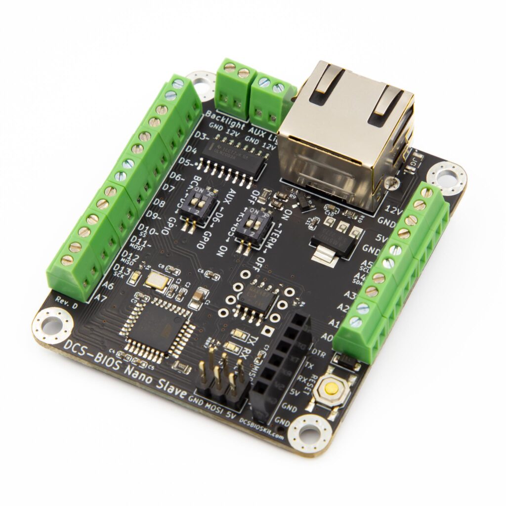
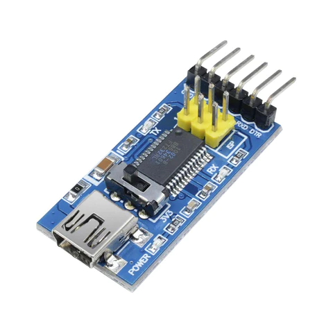
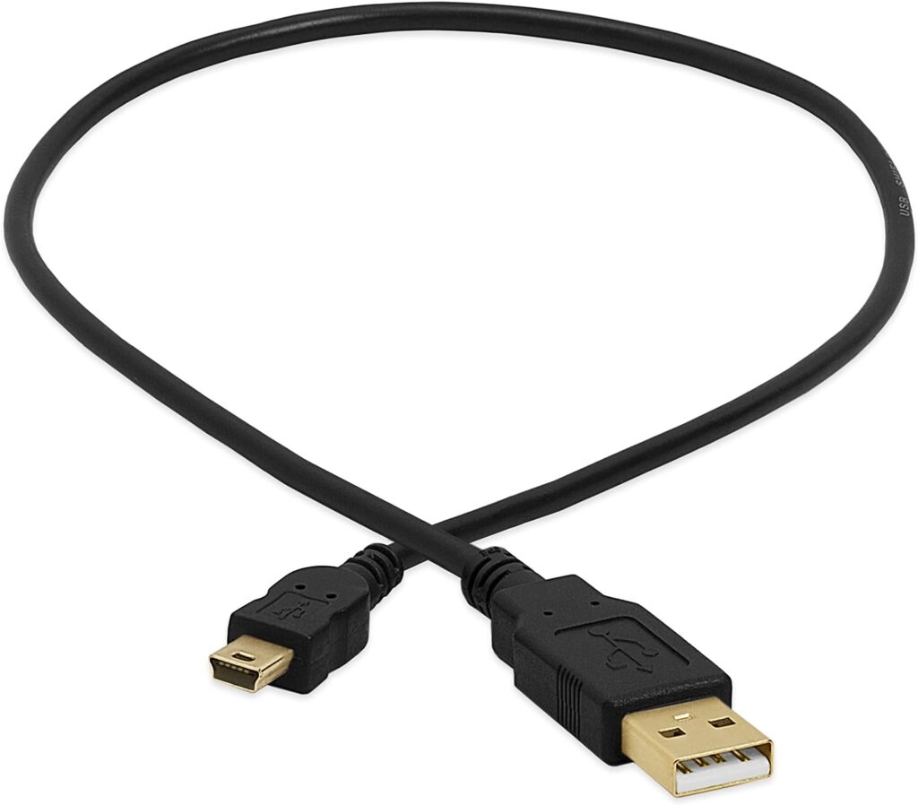
Locate the 6-pin female header on the slave controller. It is labeled UART. Observe the labeled pins DTR, TX, RX, 5V, GND & GND and insert the slave programmer to match the pins. Note that RX connects to TX, and TX to RX, so the mismatch is correct. You can use the DTR and GND pins for guidance, if they match, the connection is correct.
Caution! Never leave the Slave Programmer connected while connecting the Slave Interconnect Cable! Having both connected simultaneously may cause permanent damage.
To be able to program the controller, you may have to find the switch on the slave labeled RS485 and turn it OFF.
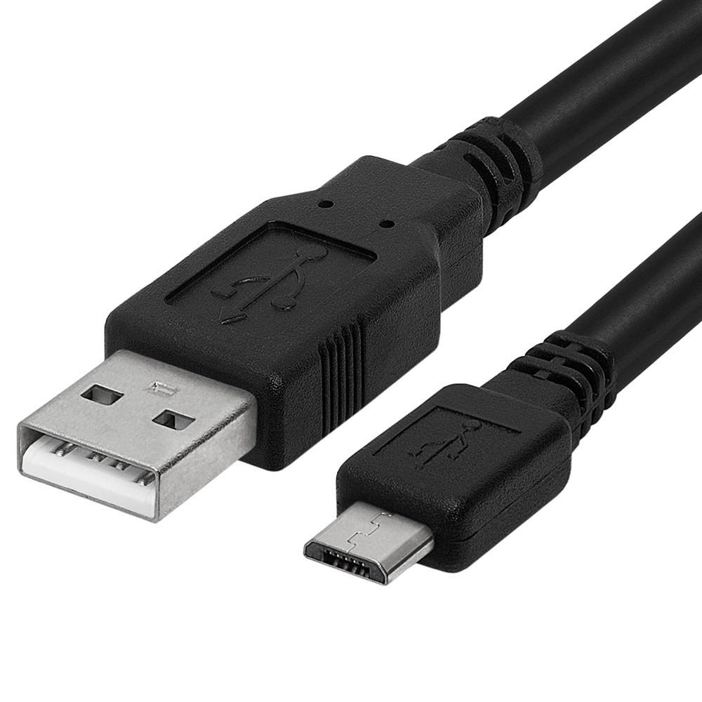
Next, plug in the mini-USB cable to the programmer, and the other end into your PC. The power LED should turn on, and the LED on pin 13 will blink once or twice depending on the type of slave controller you have.
The drivers included with Windows will not expose a COM-port, so you need to install a driver for the CH340 or FT232RL depending on the hardware revision. Instructions can be found here (CH340) and here (FT232RL). If in doubt, install both.
Open Arduino IDE, and you should now have a new COM-port listed. You can now program your slave controller just like an Arduino. A note on the Nano Slave: Please make sure that the Processor selected in Arduino IDE Tools menu is “Atmega 328P” only, without the (Old Bootloader) suffix, or programming won’t work.
To use your newly programmed control in DCS World, you need to install DCS-BIOS. If you are not familiar with the Arduino IDE and DCS-BIOS, you can follow the tutorial below. However, as your connection is not USB, please see the additional RS485 instructions below the video.
To get started and verify your setup, it is recommended to map the Master Caution light of your aircraft to an onboard LED. Below is an example for the A-10C. Please note the address and mask (0x1012, 0x0800) is only an example may change with new DCS-BIOS versions, please confirm the correct address for your airplane in Bort.
#define DCSBIOS_RS485_SLAVE 1
#define TXENABLE_PIN 2
#include "DcsBios.h"

DcsBios::LED masterCaution(0x1012, 0x0800, 13);

void setup() {
  DcsBios::setup();
}

void loop() {
  DcsBios::loop();
}
Once you have mapped some controls in Arduino IDE, you need to ensure DCS-BIOS is configured correctly for RS485. Near the top of your sketch, find the line #define DCSBIOS_IRQ_SERIAL or #define DCSBIOS_DEFAULT_SERIAL. This is not correct for DCSBIOSKit.
#define DCSBIOS_IRQ_SERIAL

#include "DcsBios.h"
Replace the line #define DCSBIOS_IRQ_SERIAL or DCSBIOS_DEFAULT_SERIAL with the following:
#define DCSBIOS_RS485_SLAVE 1
#define TXENABLE_PIN 2

#include "DcsBios.h"
The first line tells DCS-BIOS that this is a RS-485 slave device. It also sets the address of this slave device. The slave address should be between 1 and 126 and must be unique among all devices on the same bus. DCSBIOSKit has 3 buses for a maximum of 381 slaves. It is recommended to keep some space between the addresses if you need to add other devices in-between, and want to keep you numbering in order, but this is not a requirement.
The second line TXENABLE_PIN tells DCS-BIOS which pin to use to enable the RS485 transciever. This must be pin 2 and cannot be changed. Do not change this line.
With these changes, you can now upload your sketch to the slave, and remove the programmer from the slave. Remember to turn the RS485 switch back to ON.
2. Slave Connection
Required Components
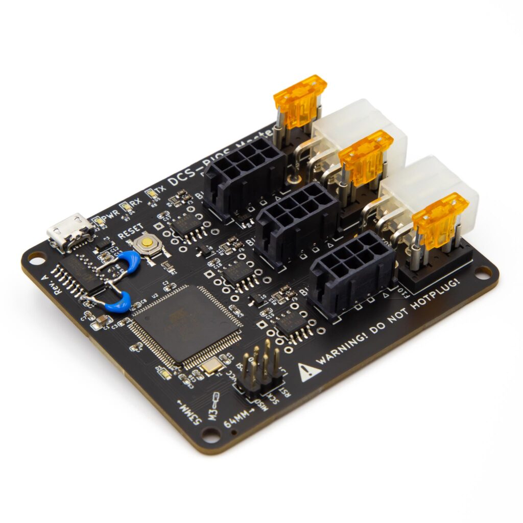
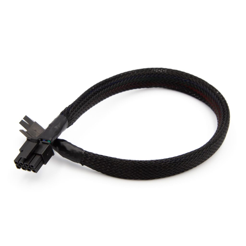
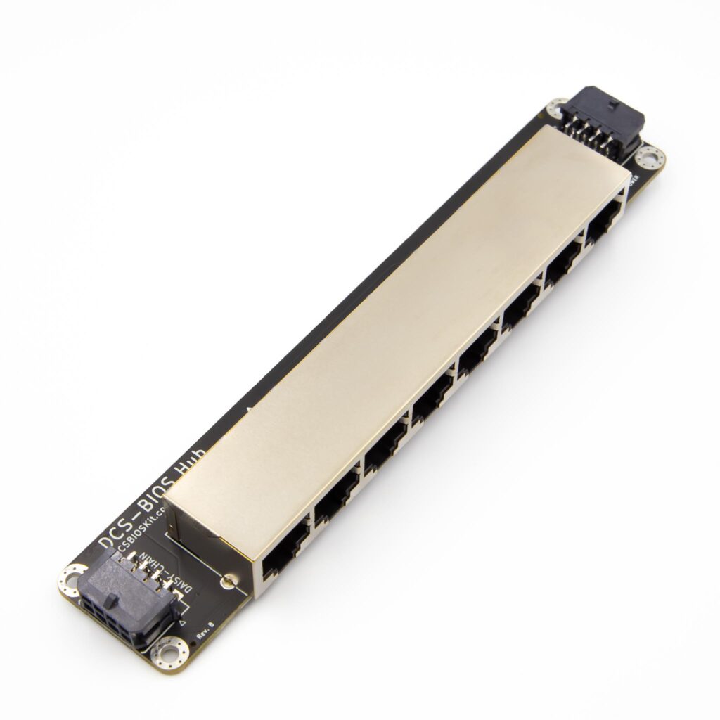
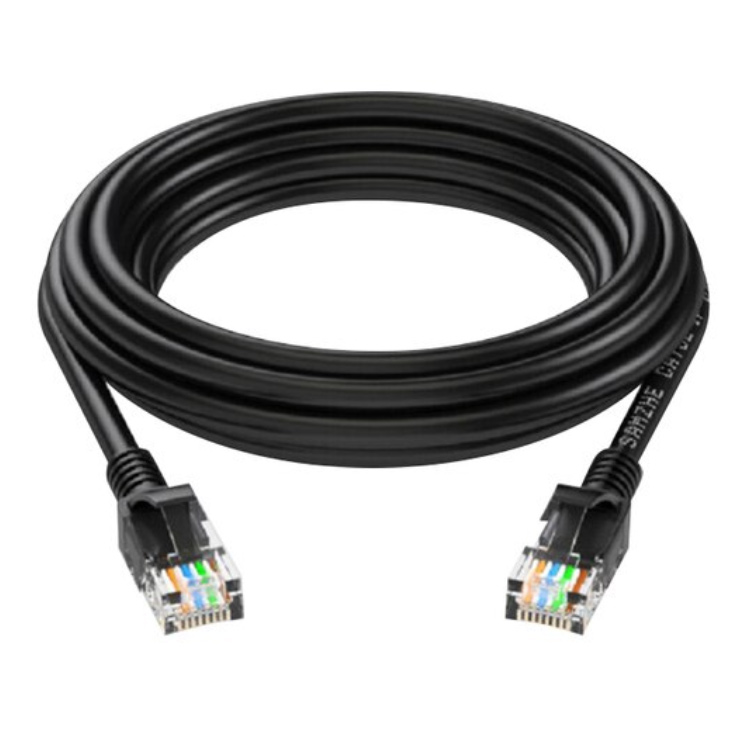

If your ATX power supply is already connected to the master controller, make sure it’s powered off. Never hotplug any connections involving the Master & Hub Interconnect Cable, or ethernet cables to avoid damage.
Connect one end of the Master & Hub Interconnect Cable to one of the Bus connections on the Master Controller. Connect the other end to the Uplink connection on the DCSBIOSKit Hub.
Connect one end of the ethernet cable to any port in the Hub, and the other end to the Slave Controller. If you use your own ethernet cables, make sure they’re not slim- or crossover type as this is not supported.
Find the switch on the slave controller labeled RS485 and turn it ON.
If you were just programming your Slave Controller, make sure the Slave Programmer is removed.
You can now power on your ATX power supply. The lights on the Master Controller and the Slave Controller should turn on.
3. Power and USB Connection
Required Components

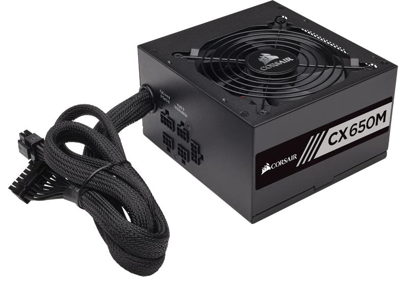
The DCSBIOSKit system is powered by a conventional ATX power supply. Any ATX power supply will do as long as it has two PCIE (graphics card) connectors. On your power supply, locate the 6-pin or 6+2-pin connectors. They are usually labeled PCIE or PCI-E. The 8-pin connector labeled CPU does not fit. If your power supply has a power switch on the back, make sure it’s turned off and disconnected from mains power.
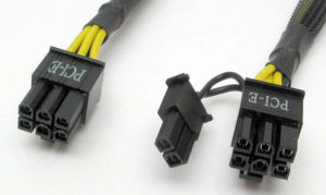
Connect the PCIE cables to the white connectors on the side of the Master Controller.
To power on an ATX power supply, you need to either short the green & black pin, or you can use a switch such as this one. If you decide to short the pins, please double-check that you are shorting the right ones.
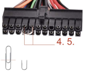
With the pins shorted, or switch in place, you can power on your power supply. Connect your power supply to mains power, and if it has a switch on the back, turn it on. You should now see 3 lights next to the white power connectors on the Master Controller.
You can now connect the Micro-USB cable to the Master Controller and your PC. The CH340C requires a driver which can be found here. Once the driver is installed, your Master Controller will appear as a COM-port.
Take care to never upload a Slave Controller sketch to the Master Controller. If you do so by accident, the original sketch can be restored from here by using Arduino IDE. Select the Arduino Mega 2560 and upload.
4. DCS-BIOS Connection
With the slave controller programmed and all connections in place, you are now ready to connect to DCS-BIOS and DCS World.
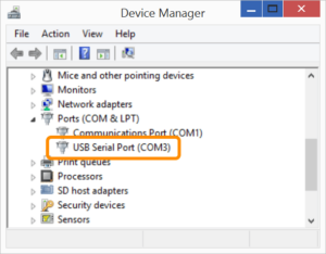
Before proceeding, make sure the USB-cable of the Slave Programmer is not connected to your PC. Open the Device Manager in Windows (⊞Win+X on your keyboard, select Device Manager). Under Ports, find the number of the COM-port of your Master Controller. If there are multiple COM-ports, you can briefly disconnect and reconnect the cable to see which one disappears and reappears. Take note of the number next to COM, in this example the number is 3.
Next, you need to launch DCS-BIOS. It is usually located in %userprofile%\Saved Games\DCS\Programs or %userprofile%\Saved Games\DCS.openbeta\Programs depending on your version. The easiest way to find it is to copy one of the paths above, open Windows Explorer, paste the path in the address bar and press enter. If you cannot find either, try opening %userprofile%\Saved Games\ and look for DCS.
In this folder, you should have connect-serial-port.cmd. Double-click it and enter the port number you found above and press enter. Only enter the number without the word COM. This window must be left open while you play DCS World. If you are having trouble with this part, it is also covered by the video above.
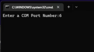
You are now ready to start DCS-World. Load into a mission with the correct aircraft for the control you mapped, and it should now work with DCS. Enjoy!
5. Advanced: Backlight
All Slave Controllers support two separate backlight channels, labeled Backlight and Auxiliary. This allows you to keep your simpit backlight in sync with DCS World. Depending on the type of controller, different Arduino pins are assigned to backlight control. The two channels use low-side control to dim the backlight via PWM, and share a common anode (+). To use the backlight driver, follow these steps:
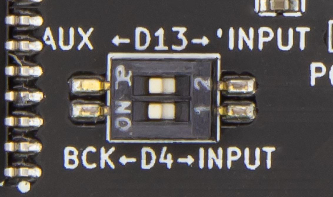
- Locate the backlight DIP-switch on the Slave Controller. It has two switches usually labeled BCK and AUX. Next to the text BCK and AUX there will be pin numbers, like D13 or D4.
- Decide which of the channels you want to use and take note of the associated pin number.
- Slide the DIP-switch for the channel you want to use towards the channel name (BCK or AUX). In this example, both channels are ON. When using a backlight channel, the corresponding Arduino pin is unavailable for other use, such as switches, and is dedicated to backlight control. Do not connect anything to the corresponding pins screw terminal, use the backlight screw terminals shown in step 4 instead.
- Locate the corresponding screw terminals on the edge of the board. They are usualy located next to the ethernet-jack and are labeled Backlight or Aux Lt. Please note that you must use the corresponding GND connection next to the 12V for each channel as the backlight driver is low side switching. If you have a lot of LEDs, you may parallel both channels.
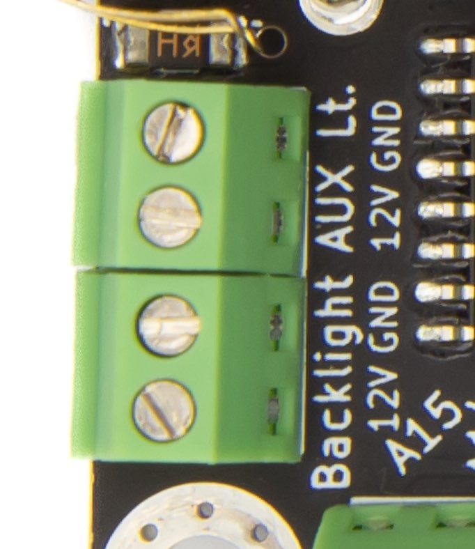
- Note the polarity on the PCB (12V, GND) and connect your LEDs accordingly. For LEDs with a forward voltage of around 3V, it is recommended to connect parallel groups of 3 LEDs in series with an appropriate resistor.
- In your Arduino Sketch, use analogWrite(PIN, VALUE) to control the brightness of the backlight. Please note that newValue from DCS-BIOS is 16-bit, and analogWrite() works with 8-bit values, so newValue needs to be divided by 256 to result in correct control. The memory address (0x12ee etc) in the example below may be outdated, please confirm the correct address for your airplane in Bort. If you are paralleling the two channels, make sure to analogWrite() to both channels simultaneously.
void onInternalConsoleLightsChange(unsigned int newValue) {
    analogWrite(13, newValue / 256); // Divide by 256 to convert 16-bit newValue to 8-bit for analogWrite()
}
DcsBios::IntegerBuffer internalConsoleLightsBuffer(0x12ee, 0xffff, 0, onInternalConsoleLightsChange);